Full Wave Inverter Circuit Diagram Inverter Sine Pure

Emilie Corkery

posts

Full Wave Inverter Circuit Diagram Inverter Sine Pure

Circuit inverter diagram wave Simple mosfet inverter circuit diagram 6 best – simple inverter circuit diagrams – diy electronics projects full wave inverter circuit diagram

Schematic structure of the full-wave rectifier under study. | Download

Inverter basic circuit diagram Inverter mosfet arduino circuits diagrams Full wave bridge rectifier circuit diagram

Inverter 4047 ic irf540 100w cd4047 220v 12vdc circuit using 12v wave 100 square 220vac watts monostable use four

Full sine wave inverter circuitSecret diagram: more circuit diagram for inverter Full sine wave inverter circuit download scientific diagramSolved build the full wave bridge rectifier circuit shown in figure.

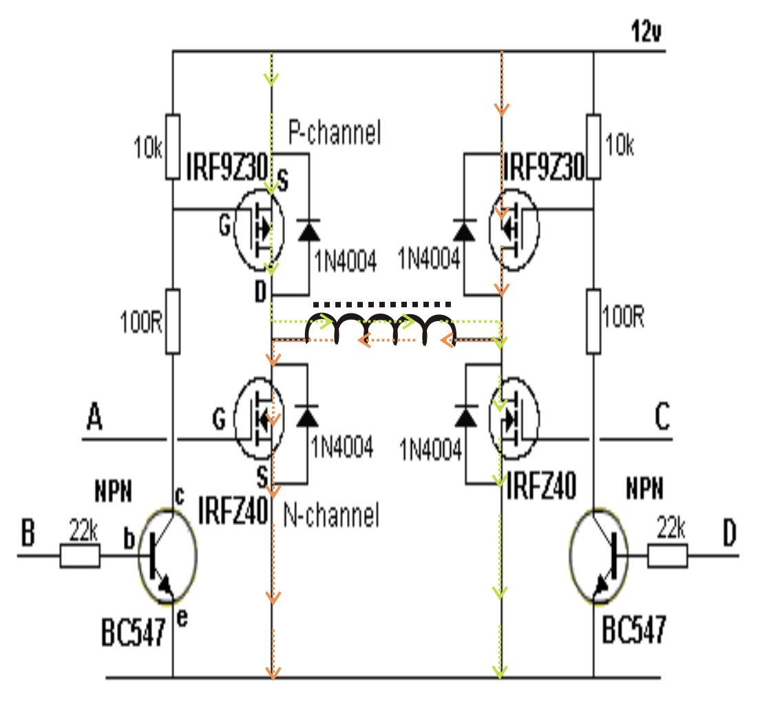
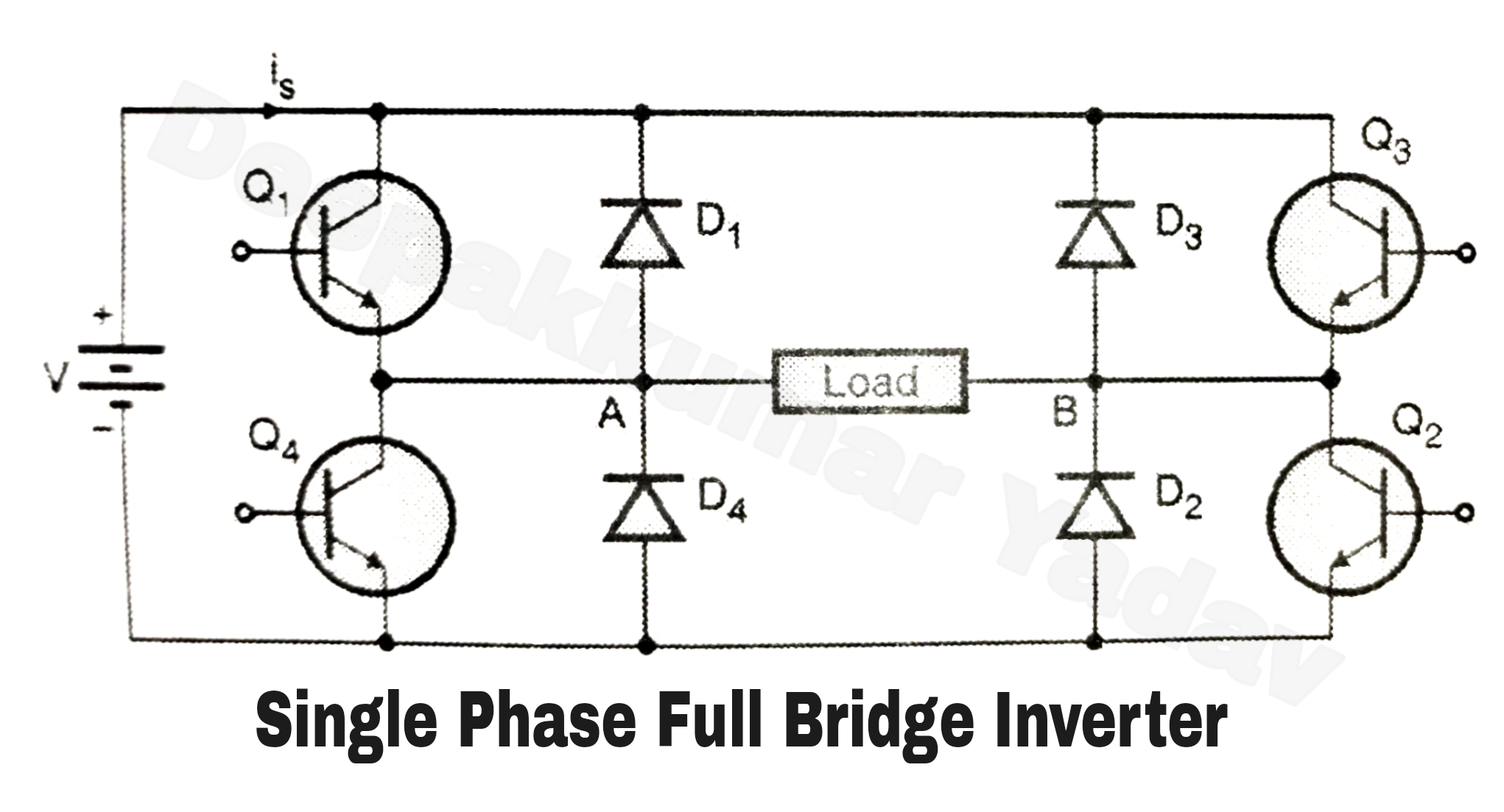
Single phase full bridge inverter (square wave output)Inverter output resistive inductive Full wave rectification diagramPure sine wave inverters.

Schematic structure of the full-wave rectifier under study. | Download

Rectifier wave bridge full circuit diagram diode voltage operation fig its shown below inverse peak disadvantages advantages value when

Inverter sine wave pure circuit diagram pwm watt simple watts controlled 1000 circuits output true sinewave voltage power mikrora diyWhat is single phase full wave controlled rectifier? working, circuit Full wave rectifier circuit working and theoryInverter voltage wave circuit diagram.

Three phase inverter circuit diagramWhat is the basic working principle of the inverter? Designing 1kw sine wave inverter circuitCircuit inverter wave sine diagram pure 2000w schematic 12v watt 1000 1kva simple parallel watts make amplifier transistors using circuits.

Full Sine Wave Inverter Circuit | Download Scientific Diagram

Pure sine wave inverter using pic16f76

300 watts pwm controlled, pure sine wave inverter circuit with outputInverter phase circuit three 120 degree mode conduction diagram dc dilip raja nov 3 high power sg3525 pure sinewave inverter circuitsIn-depth guide to full wave rectifier.

Full wave circuit diagramInverter circuit wave sine pure diagram 1kva 1000 watt watts make circuits using dc power pdf schematics eng homemade kva Inverter sine1000 watt power inverter circuit diagram.

What is the basic working principle of the inverter? - PV Power System

Inverter sine pure

Full wave rectification diagramInverter sg3525 sine circuits 3525 pure pwm watt modified low electrical schematics sinewave wiring 600va inversor 2000 pcb rangkaian correction Inverter circuit sine wave diagram board schematic solar power projects electronics arduino full inverters 1000w using diy ic charger 50hzSiwire: 2000w 12v simple inverter circuit diagram.

Full wave inverter circuit diagramSchematic structure of the full-wave rectifier under study. Full wave bridge rectifierFull wave diagram.

What Is Full Wave Rectifier Circuit Diagram Working Advantages - Riset

12v inverter circuit

Inverter voltage circuit diagram wave project electronic simple top gr next circuitsMake this 1kva (1000 watts) pure sine wave inverter circuit Four cd4047 inverter circuit 60w-100w 12vdc to 220vacWhat is full wave rectifier circuit diagram working advantages.

.

Simple Mosfet Inverter Circuit Diagram - Wiring Diagram
Inverter Basic Circuit Diagram
Make This 1KVA (1000 watts) Pure Sine Wave Inverter Circuit | Circuit
1000 Watt Power Inverter Circuit Diagram
Full Wave Bridge Rectifier - its Operation, Advantages & Disadvantages
Four CD4047 Inverter circuit 60W-100W 12VDC to 220VAC
Single Phase Full Bridge Inverter (Square Wave Output)
full wave rectification diagram - Wiring Diagram and Schematics

Also Read

Ford Super Duty Parts Diagram 96 Ford F350 Parts

Ford Super Duty Parts Diagram 96 Ford F350 Parts

Emilie Corkery

Ford f-250 super duty coil spring pocket (upper). 4wd. Ford ranger steering knuckle. Free super duty parts. [diagram] fo ...

Full Adder Circuit Diagram And Truth Table Define Combinatio

Full Adder Circuit Diagram And Truth Table Define Combinatio

Emilie Corkery

Half adder and full adder circuit. Full adder equation. Full adder circuit – how it works. Full adder circuit truth ta ...

Ford Transit Connect Ambient Air Temp Wiring Diagram Wiring

Ford Transit Connect Ambient Air Temp Wiring Diagram Wiring

Emilie Corkery

Location of ambient temperature sensor. Transit ws autorepairmanuals electrical. Ford transit-350 hvac system wiring har ...

Full Warrant And Limited Warranty Venn Diagram Implementing

Full Warrant And Limited Warranty Venn Diagram Implementing

Emilie Corkery

Law notes warranty. Condition & warranty handout 1. 1 warranty, product liability. Limited liability and warranty. Warra ...

Function Block Diagram Online 10 Useful Function Generator C

Function Block Diagram Online 10 Useful Function Generator C

Emilie Corkery

Block diagram. Free editable block diagram examples. Plc functional block diagram basics. Dcs esa fbd applications. Fbd- ...